 1
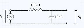
1Let us first write down the transfer function
i.e =V0Vin
H\left(j\omega \right)=\frac{1/(j\omega C)}{R+1/(j\omega C)} \\ H\left(j\omega \right)=\frac{1}{1+j(\omega CR)}
this is a complex quantity
the magnitude is
|H(j\omega)|=\frac{1}{\sqrt{1+\omega^2 C^2 R^2}} \\ \texttt{The phase lag is given by }\\ \phi=-\tan^{-1}\omega C R \\ \texttt{Since you have asked about magnitude of V(0)/V(in)} \\ \\ \boxed{V_{o}=\frac{V_{in}}{\sqrt{1+\omega^2C^2R^2}}}
Now put the values of omegas and C and R
you should get the answer [1]
 30
30[2] The unfortunate part is that I didnt get a word in your post. What exactly is a transfer function? and then the 2nd-3rd lines?
1
aditya ravichandran
·2011-06-28 02:27:12
We remember from our tutorial about Resistors in Series that different voltages can appear across each resistor depending upon the value of the resistance, as a voltage divider circuit divides the voltage by the ratio of R2/(R1+R2). Therefore, when R1 = R2 the output voltage will be half the value of the input voltage. Likewise, any value of R2 greater or less than R1 will result in a proportional change to the output voltage. Consider the circuit below.
Voltage Divider

We now know that a capacitors reactance, Xc (its complex impedance) value changes with respect to frequency. If we were to change resistor R2 above for a capacitor, the voltage drop across the two components would change as the frequency changed because of the reactance of the capacitor. The impedance of resistor R1 does not change with frequency, then the voltage across resistor R1 and therefore the output voltage is determined by the capacitive reactance of the capacitor at a given frequency resulting in a frequency-dependent voltage divider circuit. Low pass and high pass filters can be made by replacing one of the voltage divider resistors with a capacitor as shown.
Xc=1jωC
Source:http://www.electronics-tutorials.ws
30
Ashish Kothari
·2011-06-28 03:03:19
Whats the mistake in doing this?
We find the impedance of the circuit,
Z=\sqrt{R^2+X^2} where X=\frac{1}{\omega C }
V_{o}=\frac{V_{i}}{Z}\times X
since, i_{i}=\frac{V_{i}}{Z} and potential drop across the 10nF capacitor equals to Vo (I think I maybe making a mistake here but thats what it seems).
30
Ashish Kothari
·2011-06-28 03:34:34
But that seems to be giving the wrong answer!
30
Ashish Kothari
·2011-06-28 03:42:45
Ans - 8.5mV, 1.6mV, 0.16mV, 0.16μV